Tuesday, 31 March 2009

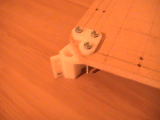
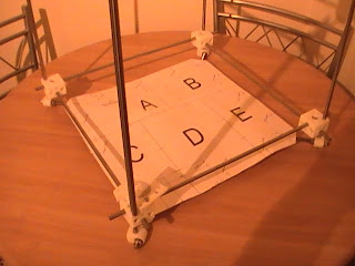
These pictures are of the buildplane/buildplatform.  There is a picture of a template, the MDF(medium density fibreboard) board, the corner mounts attatched and the assembly in place. The step after this is to install the z-posts that will raise and lower the platform.


Friday, 27 March 2009

A few more pictures showing how the top and bottom frame are separated with the vertical posts which are also M8 rods. You can also see the base diagonals which are M8 studding (threaded bar) attached with diagonal tie brackets that have been printed fixed with M8 nuts and washers.


Here are a selction of pictures where you can see how using M8 rod and M5 nuts, bolts and washers the frame starts to take shape.
The pictures show the top and bottom parts of the frame, the x-axis assembly (the middle carriage is where the extruder will be mounted) and a picture of the x-axis assembly mountd on the top frame.


Thursday, 5 March 2009

Here are a selection of parts that were built at the university on a commercial rapid prototyper. The parts are created using a CAD package by the people at reprap. The .stl files are available to download and are then fed into a computer connected to the rapid prototyper and a build is set up.

X motor Bracket


X Carriage (holds the extruder)


Y motor Bracket


All printed parts (minus a few I missed off list to build, mistake)

These parts are the main difference between my device and the Braes. These are printed parts where the Braes are laser cut.

Introduction

Hi all,
my name is Craig Barbour, I am a 4th (and final woo!) year BTechEd student at Glasgow University. I am also building a reprap machine as part of my final year project. Unlike the Braes project I have sourced the majority of the parts myself and my parts are FDM prototyped instead of laser cut parts. I think Brian said on this blog that sourcing components may be more enjoyable and satisfying, it was but so troublesome I would advise against. (Royal mail owe me circuit boards).
I will post some pictures of my progress so far so you can see how it looks and the similarities and differences between the Braes kit and mine.
Look forward to seeing the Braes progress as well and sharing news, problems and ideas
Feel free to get in touch for any info.

Craig

Friday, 12 December 2008

My visit to the Braes

Hi Guys,

Just a quick update on things.

Thoroughly enjoyed my trip through to see you all this Wednesday (10th December). It was great to meet you and to work with you for a little while.

You did some excellent work in putting the individual Reprap subsystems together. There were certainly a lot of bits to organise. I hope that the exercise of matching the drawings to the individual parts gave you all an idea of what the project entails and what we will end up with at the end.

Next thing is to work out what we do with all the spare bits that we couldn't find a home for!!

Anyway, best wishes to all the staff and pupils involved in the project and have a lovely Christmas and New Year.

Brian

Monday, 24 November 2008

The brains behind the operation

Hi all,

As promised here's a couple of images of the Arduino board and the breakout board. The boards connects to a computer through a USB connection. This allows the operation programme and part files to be uploaded onto the board and allow the prototyper to operate. So it really is the brains of the machine. The breakout board makes it easier to connect the Arduino board to other devices.

Hector's already run a quick test of the Arduino board using a little test programme and it came through with flying colours.

I'll add some more on the software and what the boards do soon.

Brian

The Arduino Board


The Breakout Board